
When I first started playing with Nuke’s Python API around 2012, one of the first things I made was a tool to align nodes in the node graph.
In fact, I wasn’t the only one, and a quick look on Nukepedia will reveal dozens and dozens of implementations of alignments tools and tools to download.
Over the years, I have grown my collection of node alignment tools, with some custom code, and by trying new ones from Nukepedia once in a while to see what new stuff they brought to the table.
I ended-up with a disparate assortment of tools, many of which re-implemented the same math multiple times. I had Frank Rueter’s mirror node, which needed to find the leftmost and rightmost edges of the selected nodes to calculate the center, I had Wouter Gilsing’s scaleTree which also needed to calculate the leftmost, rightmost, topmost and bottom most edges.
I had my auto backdrop tool, which also had the same needs as the alignment tools. Most tools had some calculations to obtain the center of a node, or place a node using the center rather than the top left corner as is the default.
I have taken this collection from studio to studio with me, sometimes for personal use, and sometimes some or all of it would make it to the studio’s pipeline. Sometimes I’d run into something cool and change my collection to implement the features I liked. Some other tools that I had added to the collection were W_smartAlign and ku_labeler.
I recently decided I would do some cleanup to my collection, to make it Python 3 compatible, and see if I could reduce the amount of duplicated code between all the functions.
As an experiment, I decided to try to use some of Qt’s native objects to help with some of these tools. Qt has a lot of built-in methods for dealing with graphics, and one in particular could prove useful: The QRect.
Using Qt for simple operations:
The QRect (for rectangle), provides some methods that could be useful to manipulate nodes. It provides direct access to the coordinates of all 4 corners of the rectangle, as well as the center. It also has methods for moving the rectangle to a new coordinate based on a specific corner, with `moveTopLeft()` being similar to nuke’s `setXYpos()`, but an additional `moveCenter()`, etc… The QRect also has a method that will tell us if the rectangle overlaps another rectangle, or contains it, or if it contains a certain coordinate.
Finally, the QRect can be grown to encompass another rectangle or provide the intersection between 2 rectangles.
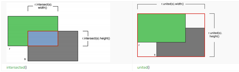
QRect intersected() and united(), from the Qt docs.
This got me thinking that each nuke Node could essentially be represented as a QRect. To get the rightmost edge of multiple nodes, all I would need to do is get the QRect for each rectangle, unite all the rectangles, and ask for the right coordinate of the united rectangle.
Let’s compare how the bounding box of multiple nodes was usually being done, to the QRect version:
Here is how Nuke’s native autobackdrop calculates the bounding rectangle and adds some margins.
selNodes = nuke.selectedNodes()

# Calculate bounds for the backdrop node.
bdX = min([node.xpos() for node in selNodes])
bdY = min([node.ypos() for node in selNodes])
bdW = max([node.xpos() + node.screenWidth() for node in selNodes]) - bdX
bdH = max([node.ypos() + node.screenHeight() for node in selNodes]) - bdY

# Expand the bounds to leave a little border. Elements are offsets for left, top, right and bottom edges respectively
left, top, right, bottom = (-10, -80, 10, 10)
bdX += left
bdY += top
bdW += (right - left)
bdH += (bottom - top)

print("Left: {}, Top: {}, Width: {}, Height: {}".format(
    bdX, bdY, bdW, bdH
))
How to achieve the same with Qt:
from PySide2 import QtCore


def get_node_rect(node):
    return QtCore.QRectF(node.xpos(), node.ypos(), node.screenWidth(), node.screenHeight())

# Get a list of all the rectangles
all_rects = [get_node_rect(n) for n in nuke.selectedNodes()]

# Unite all the rectangles
united_rect = None
for rect in all_rects:
    united_rect = united_rect.united(rect) if united_rect else rect

# Expand the bounds to add a little border.
united_rect.adjust(-10, -80, 10, 10)

print("Left: {}, Top: {}, Width: {}, Height: {}".format(
    united_rect.left(), united_rect.top(), united_rect.width(), united_rect.height()
))
While the Qt solution is not particularly shorter, I haven’t had to write any math at all, as Qt deals with it for me.
This keeps it simple so that when we get to more complex operations, I won’t have to worry too much about something in the math being wrong.
You can see how adding margins was particularly straightforward with the Qt example.
To get the center X of our new bounds, for the first example it would be `bdX + (bdW // 2)`, and for the second example it would be `united_rect.center().x()`.
Again, not that much simpler, but less mental load.
Is this completely overkill for this use case? Yes, most likely. In fact, it even executes a little bit slower due to having to instance Qt objects (I’m assuming Nuke does use QRects under the hood but it doesn’t give us direct access to them).
Taking it a few steps further
One of the tools I was never satisfied with was scaling the node graph. I have made a version back in the days that would always scale from the top left corner, and scale up or down by increments of 10% by pressing a keyboard shortcut. Wouter’s W_ScaleTree did things a lot better, but I always felt like it took me out of the flow whenever I had to use it because it’s a separate widget.
I remembered an old experiment from Michael De Caria where he had attached a QtWidget to a node in the DAG, and while he hadn’t shared his code, that confirmed it was possible, and I roughly add an idea on how to do it.
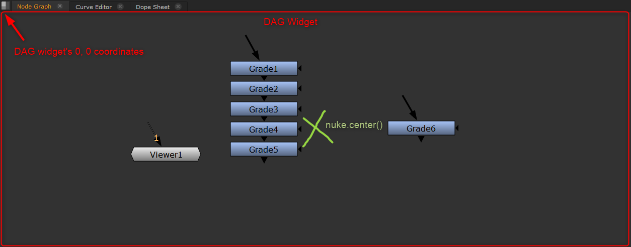
Nuke has 2 useful methods, `nuke.center()`, which tells us at which coordinate the center of the DAG currently is, and `nuke.zoom()`, which tells us how zoomed in/out we are.
There are also multiple code snippets floating around on the nuke forum to obtain the node graph’s overall widget.
By correlating the DAG’s widget and the coordinates and zoom provided by nuke, we’re able to calculate the screen space position of any nuke node:
We’ll start with 2 functions that we’ll need to get the DAG widget:
from PySide2 import QtCore, QtWidgets, QtGui
import nuke


DAG_OBJECT_NAME = "DAG"


def get_dag_widgets(visible=True):
    """
    Gets all Qt objects with DAG in the object name

    Args:
        visible (bool): Whether or not to return only visible widgets.

    Returns:
        list[QtWidgets.QWidget]
    """
    dags = []
    all_widgets = QtWidgets.QApplication.instance().allWidgets()
    for widget in all_widgets:
        if DAG_OBJECT_NAME in widget.objectName():
            if not visible or (visible and widget.isVisible()):
                dags.append(widget)
    return dags


def get_current_dag():
    """
    Returns:
        QtWidgets.QWidget: The currently active DAG
    """
    visible_dags = get_dag_widgets(visible=True)
    for dag in visible_dags:
        if dag.hasFocus():
            return dag

    # IF None had focus, and we have at least one, use the first one
    if visible_dags:
        return visible_dags[0]
    return None
I will not include these in further code snippets, but will be using them.
Let’s calculate the screen space coordinates of our DAG widget:
# Get the DAG widget
dag = get_current_dag()

# DAG coordinates:
print(dag.geometry())
# The geometry is given relative to the widget's parent, not global position, so we need to re-create a rect.
# We can create a QRect from a QPoint and a QSize.
local_rect = dag.geometry()
global_corner = dag.mapToGlobal(local_rect.topLeft())
global_rect = QtCore.QRect(global_corner, local_rect.size())
print(global_rect)
# This is better. Let's create a widget that will overlap with our DAG:
widget = QtWidgets.QDialog()
widget.setGeometry(global_rect)
widget.show()
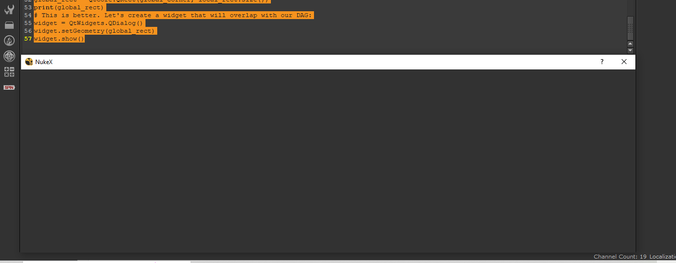
A dialog overlaid over the DAG.
Let’s recap quickly:
We know the coordinates of the node, that we obtained via our get_node_rect() function. We know the global position of our DAG, and we know that nuke.center() and nuke.zoom() can give us some info about what our DAG is looking at. These are all the ingredients we need to calculate our node’s global position.
# Get the DAG widget
dag = get_current_dag()

# The geometry is given relative to the widget's parent, not global position, so we need to re-create a rect.
# We can create a QRect from a QPoint and a QSize.
local_rect = dag.geometry()

# Find how the DAG relates to the DAG widget
# We create a QTransform, which will allow us to move our rects later.
transform = QtGui.QTransform()
scale = nuke.zoom()
offset = local_rect.center()/scale - QtCore.QPoint(*nuke.center())
transform.scale(scale, scale)
transform.translate(offset.x(), offset.y())

# This transform is relative to our DAG geometry.
# Let's check our node's position, first the original:
node = nuke.toNode('Grade1')
original_node_rect = get_node_rect(node)
print(original_node_rect)
# Map the node rect via our transform
local_node_rect = transform.mapRect(original_node_rect)
print(local_node_rect)
# Now map to global. There is no built in method to map a rect to global, only a point, so we do the same procedure
# as we did for the DAG geometry, mapping the top left corner and building a new rect out of it.
corner = dag.mapToGlobal(local_node_rect.topLeft().toPoint())  # We use .toPoint() as mapToGlobal expects a QPoint, not a QPointF.
global_node_rect = QtCore.QRectF(corner, local_node_rect.size())

# Make a widget to overlay over our grade.
widget = QtWidgets.QLineEdit()  # I make it a QlineEdit this time otherwise it blends in with the background
widget.setGeometry(global_node_rect.toRect())  # We use .toRect() to convert back to a regular QRect, not a QRectF, as we need integer values.
# Remove the widget's frame/window, so that it doesn't have a minimum size.
widget.setWindowFlags(QtCore.Qt.Window | QtCore.Qt.FramelessWindowHint)
widget.show()
A QlineEdit perfectly lined up with my Grade Node.
At this point, we have the building pieces to draw more or less what we want.
A few examples of what I did with it:
Scale Widget:
Scale Widget
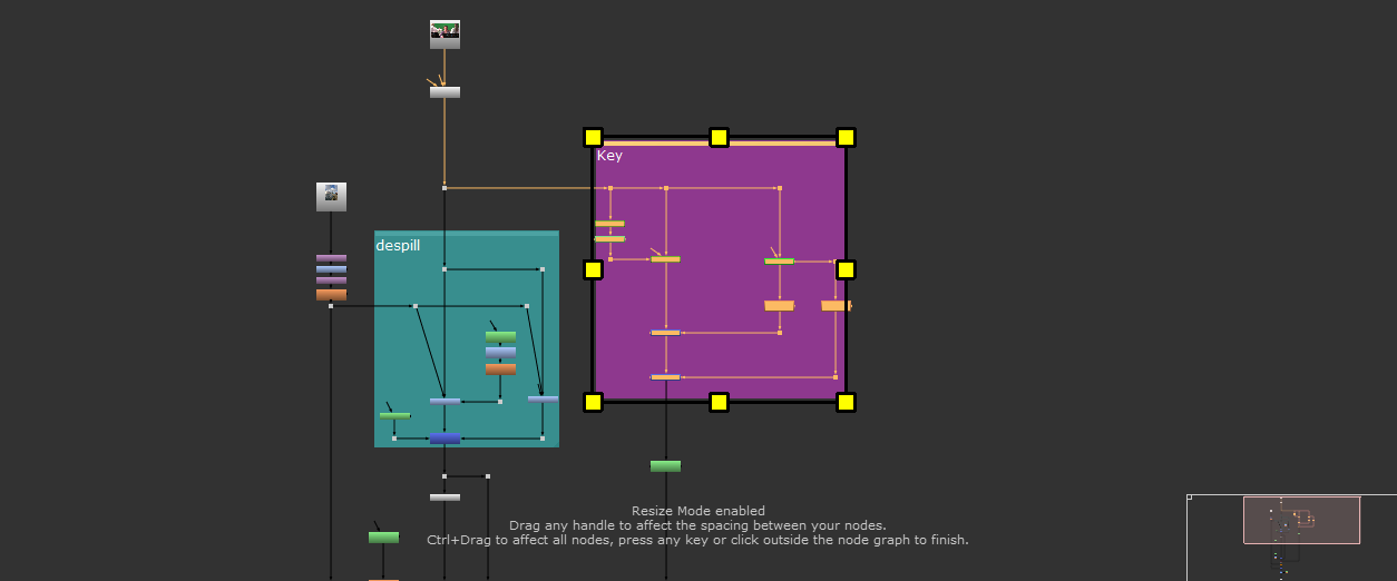
Using some of the methods explained above, I create a transparent widget that lines up perfectly over the DAG, and on this widget, I draw some rectangles.
I loop over the selected nodes to get all the rects of the selected nodes and unite them as we did at the beginning, then I draw small rectangles at the corners to be used as handles.
The whole interaction with the widget is a bit out of the scope of this post, but you can see the whole code here: https://github.com/herronelou/nuke_nodegraph_utils/blob/main/node_graph_utils/scale_widget.py
Node connection cutting:

Snippy
This one reuses a lot of the code of the scale widget, and also creates a transparent widget over the DAG.
Instead of drawing rectangles, I made a simplified paint canvas, based on a tutorial like https://www.pythonguis.com/tutorials/pyside-bitmap-graphics/ (I read a few different ones, can’t recall if this is exactly the one I used as a base).
This draws tiny lines every time the mouse moves while being clicked, and for each line, it checks if that drawn line intersects with the lines of the node connections.
The connections can be obtained by creating a QLine based on 2 nodes’ centers.
Code here: https://github.com/herronelou/nuke_nodegraph_utils/blob/main/node_graph_utils/snippy.py
Inserting images in the graph
Just for fun, using almost the same code as we used to overlay a widget with a node, we can place a widget next to it, or above it by affecting the coordinates:
Here I switched to importing the convenience methods from my node_graph_utils library, as it can handle backdrops.
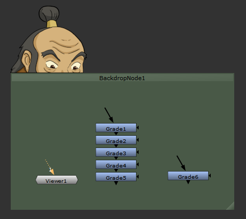
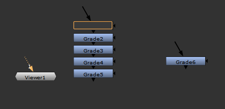
It’s time for you to look inwards, and ask yourself the big question: What’s the point of five Grade nodes with no input?
from Qt import QtCore, QtGui, QtWidgets
from node_graph_utils.dag import get_node_bounds, get_current_dag

# Get the DAG widget
dag = get_current_dag()

image = r'C:\Users\herro\Downloads\iroh.png'

# The geometry is given relative to the widget's parent, not global position, so we need to re-create a rect.
# We can create a QRect from a QPoint and a QSize.
local_rect = dag.geometry()

# Find how the DAG relates to the DAG widget
# We create a QTransform, which will allow us to move our rects later.
transform = QtGui.QTransform()
scale = nuke.zoom()
offset = local_rect.center()/scale - QtCore.QPoint(*nuke.center())
transform.scale(scale, scale)
transform.translate(offset.x(), offset.y())

node = nuke.toNode('BackdropNode1')
# This transform is relative to our DAG geometry.
# Let's check our node's position, first the original:
original_node_rect = get_node_bounds(node)
# Map the node rect via our transform
local_node_rect = transform.mapRect(original_node_rect)
# Now map to global. There is no built in method to map a rect to global, only a point, so we do the same procedure
# as we did for the DAG geometry, mapping the top left corner and building a new rect out of it.
corner = dag.mapToGlobal(local_node_rect.topLeft().toPoint())  # We use .toPoint() as mapToGlobal expects a QPoint, not a QPointF.

# Make a widget to overlay over our grade.
widget = QtWidgets.QLabel()
pixmap = QtGui.QPixmap(image)
widget.setPixmap(pixmap)
rect = QtCore.QRect(corner, pixmap.size())
rect.moveBottomLeft(corner)
widget.setGeometry(rect)  # We use .toRect() to convert back to a regular QRect, not a QRectF, as we need integer values.
# Remove the widget's frame/window, and make the background transparent.
widget.setWindowFlags(QtCore.Qt.Window | QtCore.Qt.FramelessWindowHint)
widget.setAttribute(QtCore.Qt.WA_TranslucentBackground)
widget.show()
Great post, I found this very informative and would be using this as a starting point for any future DAG customisations
Fall in love with Scale Widget thanks !
Great!
I think it would be useful to use the same paint canvas method to make Lasso selection in the Node Graph.
For example to organize a messy script.
I think you could do it, yes. I don’t know how to test whether something is inside or outside an arbitrary shape but I’m sure there are pre made algorithms out there.
This is so cool! I learned something completely new