
I was reading the excellent blog DoingThatWrong by Dan Sturm (who I don’t personally know) and saw his article about Rounded Rectangles.
As I was reading the article and downloaded the tool, I wondered how I would have made a similar tool, and how to get around the limitations Dan is pointing out in his article.
My first instinct would have been to go with a Bezier shape, so that’s what I did for this tool. If you just want to download the pre-made tool (for Nuke 9), you can go straight to the bottom of this page. If you’re interested in learning how to make similar tools by yourself, just follow along!
The idea
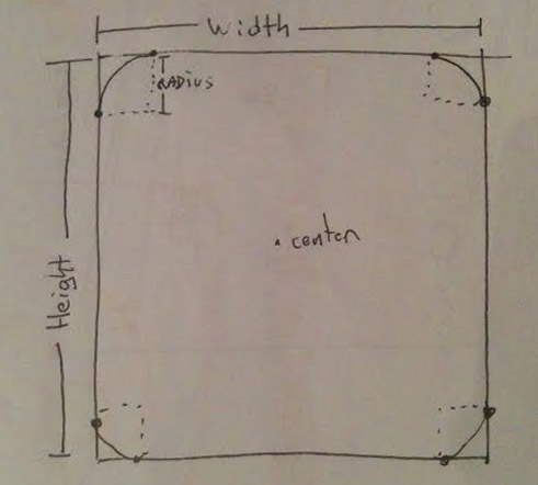
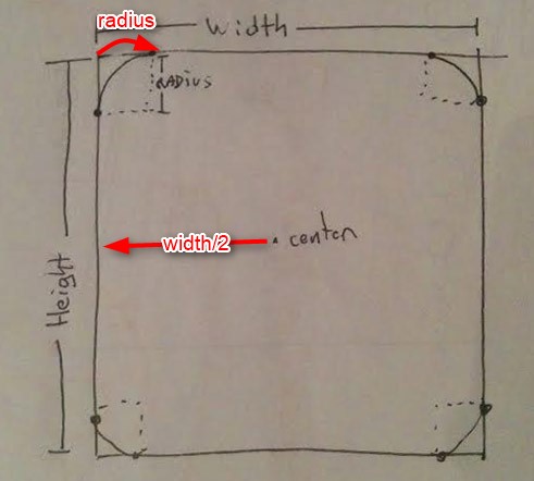
Impressive sketch of a rounded rectangle.
It seemed to me that the easiest way to create a Rounded Rectangle, or any shape for that mater, would be to use a Roto node.
As we can see in the sketch above, a rounded rectangle would in fact be a shape with 8 points (2 for each corner) and a nice curve in each corner.
Making the basic Shape and it’s expressions
I started by making a Roto node.
Because we’re making a tool and we’re likely to want to add custom knobs on the way, I grouped this node (ctrl+g on windows/linux). We can also see from the drawing that we will most likely at least need a knob for width/height, and one for radius. Right click on the group’s properties panel and select “Manage User Knobs”.
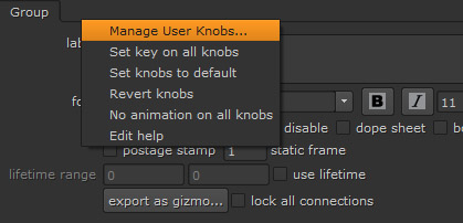
Or you could add the knobs with Python. If you’re one of my 4 dedicated readers, you should know how to do it by now.
Then add a width/height node that we could name “size”, and a floating point slider named “radius”, with a minimum value of 0 and a maximum of 150.
Note that you could name this whatever you wanted, but if you change the name, you’ll need to adjust the expressions coming in later on accordingly.
When you created your first knob, nuke also automatically created one called “User”. This corresponds to the Tab it created in the properties Panel. Feel free to rename this to a name that makes sense. I named mine “Rounded Rectangle”.
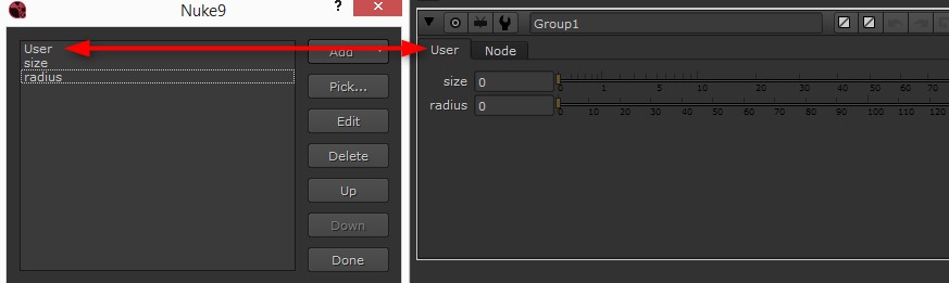
Once you’re happy with your knobs, just click Done to close the panel.
Get inside your group and select your Roto (your group’s node graph should already be open, but just in case, you can re-open it by clicking the “S” Icon in the group’s properties panel).
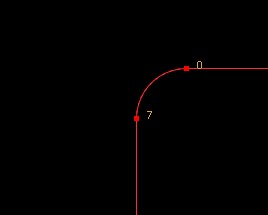
Let’s create a shape with 8 points. I’m making mine with a cusped Bezier just for simplicity, but a regular Bezier would work as well.
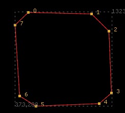
We will need to add expressions to all these points. Just from looking at them, we can deduce a few things though:
0 & 1 will share the same Y value, just like 7 & 2, 6 & 3 and 5 & 4.
7 & 6 will share the same X value, just like 0 & 5, 1 & 4 and 2 & 3.
It means we have 4 expressions to find for X, and 4 for Y.
Let’s look back at our first sketch.
And everyone told me I would never use middle school geometry lessons in real life.
We can see that the X position of point 0 could be found by finding the center, moving half of the width to the left, then the same amount as the radius to the right.
The center could be any value we wanted, but in this case we will make it the center of our image. In nuke you can use width and height in an expression, which gives you the resolution of your image. So in order to find the center of our screen in X, we would use width/2. (Again, this is the width of the image, not the rectangle)
For the width of our rectangle, we will decide that value in the “size” knob that we created earlier. Right now the value should be 0 as we just created the knob. Let’s just put a value of 1000 in there for the time being. Let’s also give a value to the radius knob other than 0, say 50.
To access a knob on a group from within a group, the expression is parent.knobName. Here we want to access the “size” knob, in particular the width part of it in case it’s not equal in width/height, so our expression will be parent.size.h .
Following the same logic, the expression for the radius would be parent.radius .
To add an expression to a point, select it, right click on it, and select “add expression”. This barbaric panel should open:
[/fusion_builder_column]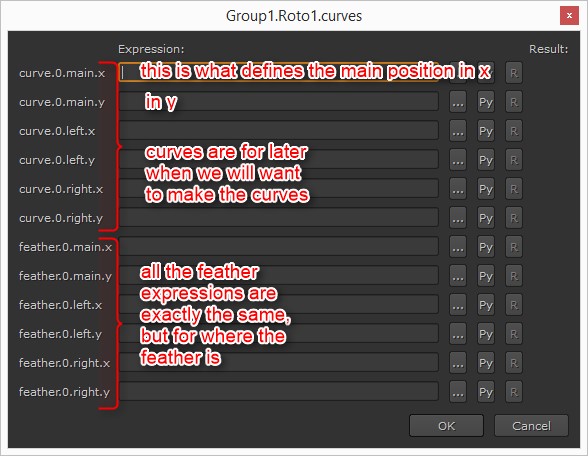
You can see the developers did a good job naming knobs when my explanations don’t actually make the image any clearer.
What I said earlier, take center, move to the left, to the right, to the left, put your hands in the air and jump, that doesn’t make much sense for the computer.
But we could easily translate that to: “coordinate of the center – half of width + size of radius”.
From the expressions I showed earlier, that would be translated to: (width/2) – (parent.size.w/2) + parent.radius divisions have the priority over additions and subtractions, so the parenthesis are optional, but they don’t hurt either for readability. Go ahead and type that in the panel. (Copy and paste from my website seems to embed some html elements and didn’t work for me)
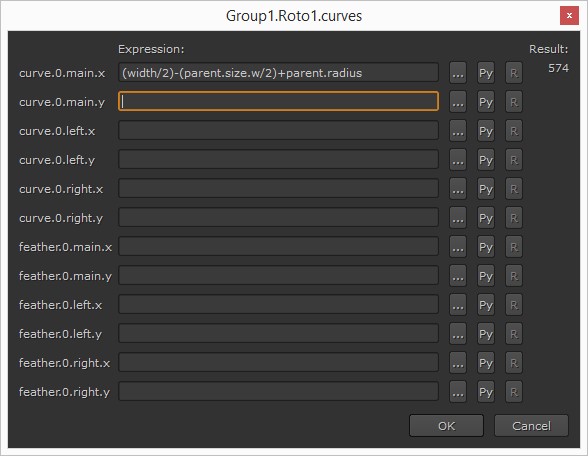
You can go ahead and copy the same expression into dot 5.
Try to find the expressions for the other dots (just X and Y) by yourself.
Hope you tried it yourself, otherwise, here are the answers:
X for 1 and 4: (width/2) + (parent.size.w/2) – parent.radius
X for 2 and 3: (width/2) + (parent.size.w/2)
X for 6 and 7: (width/2) – (parent.size.w/2)
Y for 0 and 1: (height/2) + (parent.size.h/2)
Y for 7 and 2: (height/2) + (parent.size.h/2) – parent.radius
Y for 6 and 3:(height/2) – (parent.size.h/2) + parent.radius
Y for 5 and 4:(height/2) – (parent.size.h/2)
Once you have added all these expressions, your shape should now look like that:
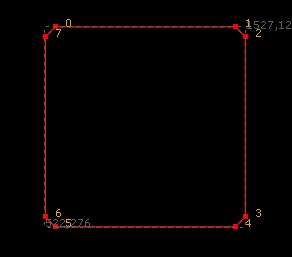
Much Cleaner than my original shape.
Rounding the corners
I actually quite like the option to have a bevel on the corners without rounding them, so I decided to add a floating point knob (between 0 and 1) to decide how much rounding to do on the corners. 0 would be s sharp bevel like our current shape, 1 would be a perfectly rounded corner.
I repeated the same operation we did earlier to add our “size” and “radius” knobs, and added a “rounding” one.
I was wondering, based on the radius, how much should I pull my Bezier handles in order to get a perfect circular arc. Since I don’t know exactly the math behind Bezier curves, I googled it and found this article: http://spencermortensen.com/articles/bezier-circle/
I skipped all the heavy math and went straight to the answer, the magical value 0.551915024494. Which I rounded up to 0.552.
It’s not perfect perfect, but that will do.
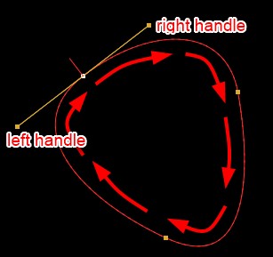
All the arrows show us the “flow” of the control points. Each one of the arrow is showing us what nuke considers to be Left to Right. As you can see, for a point at the bottom of the shape, the left handle would actually be on the right side of the screen. Is that clear?
So, back to my point 0.
The curve handles X and Y we can specify in the expression are values that are relative to the main X and Y.
If the coordinates are 0, we have a cusped curve, or no curve at all, since the curve and the corner are overlapping.
From the magical number we got earlier, the expression for curve.0.left.x would be radius*0.552.
However, I’d like to be able to control how much rounding it gets with my “rounding” knob, and we also need to make sure the left handle goes to the left (negative X) so I made the expression: -radius*0.552*parent.rounding.
If you set your rounding knob to 1 now, you will see a curve started to appear on dot 0. It’s not perfectly round yet, and there is also something strange happening with the feather. The reason for that is that the feather curve is also relative to the main point, and not to the curve points you just modified. In order to sort the feather issue, fill the expression like so:
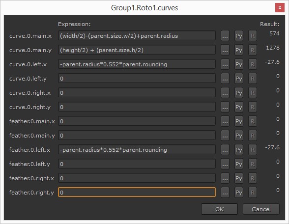
Putting 0 as expression in the other fields makes them un-editable manually, which ensures us in that case the user won’t accidentally open the roto node and edit the shape.
In order for the corner to be a perfect circular arc, we also need to enter the expression in point 7. It will go this time in curve.7.right.y, and the expression will be radius*0.552*parent.rounding. Almost the same, without the minus. Same thing will go in feather.7.right.y.
Boom, perfect rounded corner.
Go ahead and fill out the other expressions for each corner. I won’t give you the answers this time, as it would take a while for me to type them all, and they are all pretty much the same, with our without the minus sign. If you see your curve going the wrong way, you probably mixed up left and right, or X and Y, or + and -. Go on, I believe in you.
Once you’re done, you should already be left with a working rounded rectangle. You can play with your knobs to check everything is working properly. You can try pushing the rounding past 0 and 1 to see what happens, it’s been creating interesting shapes for me. Although if you want a rounded rectangle, you should probably keep it at 1.
Adding options to our rounded rectangle
You could add more knobs to your parent Group for additional control. Here is what I added to mine:
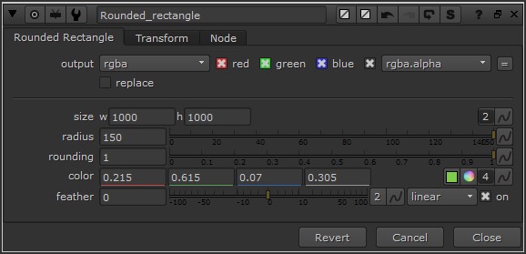
For each Knob you add, you have the option to pick and existing one from within the group, pick and expression link, or create a blank one and make the expression yourself.
I’ll walk you through what I did:
output: “Pick.. > Roto1 > Roto > output”.
replace: “Pick.. > Roto1 > Roto > replace”.
separator : Choose “Add > Separator”.
size, radius, rounding: These are the knobs we previously created.
color: I created an empty RGBA color picker, then went into my shape controls, separated the color option into 4, and added the expressions parent.color.r, parent.color.g, parent.color.b and parent.color.a.
feather: “Pick.. > Roto1 > Roto > feather” and expression link
feather type: “Pick.. > Roto1 > Roto > feather_type” and expression link. The list came in empty, so I re-entered “linear, smooth0, smooth1 and smooth”, each on a separate line.
on: “Pick.. > Roto1 > Roto > on” and expression link
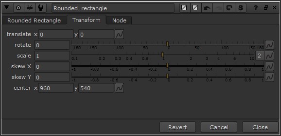
I then added a tab, labeled “Transform”.
Within the group, I created a Blank Transform node. And expression linked all the transforms of the roto shape to that transform node. Then from my “manage custom knobs” on the group, I picked the knobs from the transform node. (translate, rotate, scale, skew X and Y, center).
The reason why I added a transform instead of picking directly the roto node’s knobs, is that the roto knobs are sensitive to what is selected within the node. I kept getting greyed out knobs, so I decided to get around the issue this way.
Limitations
I did not add Motion Blur controls at the moment because of a bug that causes Nuke to crash when I try to expression link one of the motion blur knobs. Will update when the foundry gets back to me. You could still add motion_blur controls yourself if you wanted them , but stay clear of the ‘motionblur_shutter_offset_type’ knob for now.
Edit: I had to also lock the shapes in the Roto node, because for some reason, once added via a toolset (or copy/pasted) the node was defaulting to add shapes in the roto. Locking it prevented errors.
Lovely. Only issue I noticed is that it doesn’t support non square pixel aspect ratios correctly. Divided some of the X axis expressions by “format.pixel_aspect” to correct it.
I can’t believe this gizmo is over 10 years old now. I’ve been using it on pretty much every project since you made it, so thank you again for this awesome tool.
I’m not sure if you’ve run into it yet, but something in Nuke16 broke the expression linking in this thing. I think it’s something to do with how they changed the group nodes, but I haven’t been able to figure out what’s going yet. Do you have any ideas why it broke / what’s different about groups now?
He Dan.
Sorry for the delay. I’m not sure what broke, I haven’t fully updated to 16 yet, I’ll try to remember to take a look when I update.